Megasquirt® Relay and Power Distribution Board
This page contains information on the MegaSquirt Relay/Power Distribution board for the MegaSquirt® EFI system. The relay/power board is designed to be installed in the engine compartment and interconnected to the MegaSquirt® ECU using a remote cable. This allows the mounting of the MegaSquirt® ECU in the passenger compartment, which keeps the ECU from experiencing the severe under hood temperatures that exist in most installations. The relay/power board provides a solution for all of the fusing and high-current switching requirements needed for a complete MegaSquirt® ECU installation.
Features of the Relay/Power Board include:
Three on-board relays - main power, fuel pump, and fast idle solenoid
Four Mini-ATO-style fuses (Buss Fuse ATM-XX) protect the fuel pump, main power, and both injector banks
Three Raychem Polyfuse Circuit Protector devices protect the ECU main power and Vref +5V supply from shorts and overcurrent situations.
Idle solenoid drive source is jumpered on the board to allow the use of either grounded solenoids or units which are supplied with external +12 volts.
A 20-position terminal strip breaks out all under hood sensors, as well as both injector drive banks, fuel pump, and idle solenoid. Wiring of all external devices is greatly simplified - each position is clearly marked to reduce wiring mistakes and ease wire tracing.
A 4-position terminal strip provides fused power (+12V) for both injector banks.
The +12 Volt battery (both switched and unswitched) and engine ground are broken out as single pads on the PCB and supply the entire power needs for the MegaSquirt ECU, injectors, relays, idle solenoid, and fuel pump. This single-point entry point for power greatly reduces the risk of accidental wiring mistakes.
The board provides a separate return ground path back to the MegaSquirt ECU for the coolant/air temperature and TPS sensors, preventing possible ground loop situations.
Board fits in a 3 x 5 inch LMB case - very compact!
Download Files for the MegaSquirt® Relay/Power Distribution board:
MS Power/Relay Board Schematics in PDF Format
MS Power/Relay Board PCB Layout in PDF format
MS Power/Relay Board -Picture of Completed Unit
"How to Make the Cable", and Relay Board Testing
MegaSquirt® Relay Bill Of Materials
QTY   Description
-------------------------
(3)  -  Relay Socket - VCF4-1000
(3)  -  Relays -  VF4-11F11
(4)  -  ATO Fuse Socket - Littlefuse 153008
(4)  -  RXE105 or RXE110 - Raychem Polyfuse
(2)  -  10 Terminal Block -  Two Sections (interlock together to make 20-terminals)
(1)  -  2 Terminal Block  (interlock together to make 4-terminals)
(1)  -  DB-37 male PCB-mount connector
(1)  -  LMB-Heeger case
(1)  -  PCB
MegaSquirt® Relay Board DB-37 Pin Connections
| DB37 pin #1 | ground/not used |
| DB37 pin #2 | ground/not used |
| DB37 pin #3 | SPR1 (CANH)
Connect MegaSquirt® end only |
| DB37 pin #4 | SPR2 (CANL)
Connect MegaSquirt® end only |
| DB37 pin #5 | SPR3 |
| DB37 pin #6 | SPR4 |
| DB37 pin #7 | Ground |
| DB37 pin #8 | Ground |
| DB37 pin #9 | Ground |
| DB37 pin #10 | Ground |
| DB37 pin #11 | Ground |
| DB37 pin #12 | ground/not used |
| DB37 pin #13 | ground/not used |
| DB37 pin #14 | ground/not used |
| DB37 pin #15 | ground/not used |
| DB37 pin #16 | ground/not used |
| DB37 pin #17 | ground/not used |
| DB37 pin #18 | ground/not used |
| DB37 pin #19 | Sensor Ground |
| DB37 pin #20 | Intake Air Temp. (IAT) sensor |
| DB37 pin #21 | Coolant Temp. (CLT) sensor |
| DB37 pin #22 | Throttle Position sensor (TPS) |
| DB37 pin #23 | EGO (O2) sensor |
| DB37 pin #24 | Tach (Ignition Input) |
| DB37 pin #25 | IAC 1A |
| DB37 pin #26 | Vref (+5V output) |
| DB37 pin #27 | IAC 1B |
| DB37 pin #28 | +12V Supply |
| DB37 pin #29 | IAC 2A |
| DB37 pin #30 | Fast Idle (FIdle) |
| DB37 pin #31 | IAC 2B |
| DB37 pin #32 | Injector Driver #1 (INJ1) |
| DB37 pin #33 | Injector Driver #1 (INJ1) |
| DB37 pin #34 | Injector Driver #2 (INJ2) |
| DB37 pin #35 | Injector Driver #2 (INJ2) |
| DB37 pin #36 | Ignition Output |
| DB37 pin #37 | Fuel Pump (FP) |
MegaSquirt® Relay/Power Board Q&A:
Q: Do I have to use the MegaSquirt® Relay/Power board for my setup?
A: No, it is not absolutely required for a MegaSquirt® installation. But, it helps ease installation with all of the underhood wiring, as well as relay mounting, fusing, etc.
Q: Where does the Relay/Power board mount in relation to the MegaSquirt® ECU?
A: The Relay/Power box is designed to be mounted under hood, near the engine and sensors. The MegaSquirt ECU should be mounted inside of the passenger compartment, away from engine heat. The Relay/Power board is connected to the MegaSquirt® ECU using a multi-conductor cable assembly and two DB-37 connectors.
Q: Can I directly plug the Relay/Power box into the MegaSquirt® ECU without a cable?
A: No, not directly. Both the MegaSquirt® and the Relay/Power box use DB-37 male connectors, each with the same pins for the same function. You have to use a connecting cable, each with DB-37 female connectors on each end.
Q: Why are the connectors this way?
A: For many reasons - the main one is to prevent the temptation of just plugging the two units (MegaSquirt® and the Relay/Power board) physically together and mounting in this fashion. Fixed mounting in this arrangement of two boards thru a DB-37 connector will lead to board stresses during mounting / operation, and inevitable long term failure. In addition, the relay board is designed to be mounted under hood, near the engine and sensors, whereas the MegaSquirt ECU should be mounted in a temperature-controlled environment - this requires the use of a cable.
Using the same connector/gender on each end of the cable simplifies connector wiring. When you wire up each end of the cable to DB-37 female connectors, you can hold the two connectors right next to each other and verify correct wiring - both will have the same wire going into the same pin - instant verification, and no mirror-images to deal with. When you have 20 wires to deal with, it is nice to have a simple way of verifying wire location.
Q: Which pins do I need to connect on the DB-37 female cable (both ends)?
A: You need to connect pins 7, 8, 9, 10, 11, and 19 - 37 (all), plus 3 and 4 should be connected at the MegaSquirt ® end and left loose (do not connect at the relay board end - they will connect to the other controller) for CAN communication if desired with MS-II and auxillary boards.
Q: What wire gauge do I need?
A: For everything other than pins 32, 33, 34, 35 (injector drive pins), you can use 20 gauge (AWG) wire for short runs (10 feet) - for longer runs use 18 gauge. For the injector drive pins, saturated injector setups can use 18 - 20 gauge wire (depending on insulation type), and low-impedance injectors should use 18 - 16 gauge.
Try looking locally for heating/air conditioning HVAC plenum-routed control wiring - you can often find multi-conductor cable in the 18-20 gauge size. HVAC wiring is ideal in that it usually employs teflon insulation and is designed for high heat applications. Also, look at the following links from Alpha Wire:
Link for wire insulation descriptions and uses
Link for a chart of current-carrying capacity of copper conductors
Q: Which case is used for board mounting?
A: The Relay/Power board uses one half of a LMB EAS-200. The case comes apart in halves (top and bottom) when you remove the end plates. The Relay/Power PCB slides into one of the case halves, and is held in place with the end plates - one plate is cut in half and used on both sides. The top of the LMB case is not tall enough to clear the relays, so it is not used.
Q: So, this means that the top of the board is exposed?
A: Yes, but this is acceptable in a engine bay environment. The unit is mounted under hood, so the likelihood of accidental shorts, contacts to foreign objects, etc. is the same as with any other engine component (starter, alternator, fuse block, etc). The PCB has a solder mask layer which will provide some protection, and the user can coat the finished board with conformal coating or polyurethane before mounting in the case. In addition, all circuits are fused, so an accidental contact will cause a fuse or polyswitch device to open. One thing to remember is to drill a small (1/8") hole in the bottom-side of the case to allow the escape of moisture from the backside of the PCB/case interior.
Q: What are these Polyfuse devices?
A: Raychem (www.raychem.com) makes these devices which are resettable fuses. They are made of a polymer which, when heated above a certain point, exhibits a high resistance, which reduces current flow. When cooled, they go back to a low-resistance state, hence a resettable fuse!
Q: What is the "G and V" jumper pads on the PCB?
A: If you look at the schematic, you will see that the fast-idle relay contact can be jumpered to either supply +12V when the relay is closed,
or supply gound when the relay is closed. These are the jumper pads for this. If you want the relay to provide +12V when it closes (i.e. the
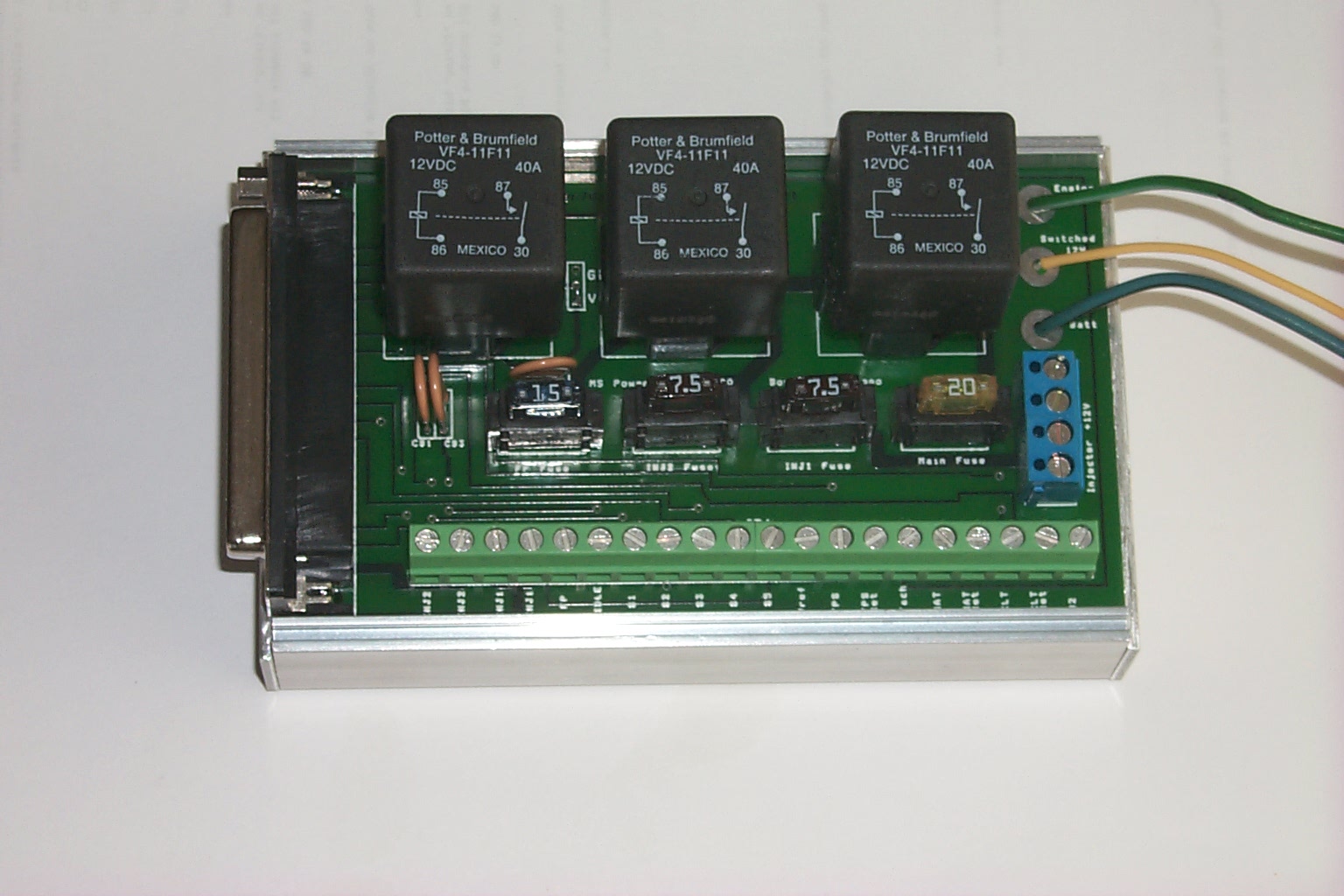
fast idle solenoid is grounded on the other end), then put a jumper between the "V" and center terminals - look at the photo link above to see this.
If you want the relay to provide ground when closed, then place the jumper from the "G" terminal to the center one. This is the only jumper on the board.
Q: Anything to watch out for during assembly?
A: No, the unit is really easy to assemble - look at the photo for guidance during assembly. One thing to note is that the relays may be of
different manufacture than the picture, so the printing on them may be upside down when installed - this is O.K. The relay sockets go in the
PCB "comfortably" in only one position - the pin that goes to the right is a tad longer than the other three pins on the perimeter of the socket -
the right side (and top and bottom) sockets form a "dash" symbol, while the left-side and center terminal form a "vertical bar" - look
at the socket jack slots to see what I mean.
There are two positions of screw-terminal strips. The blue ones on the right are for providing +12V to the injectors - these are fused on the board.
The green connector (bottom, 20-position) is used to make connections to all of the sensors, fuel pump, injector drives, etc. Both of these connectors
are very rugged and they will not loosen up for normal conditions. However, for extreme vibration applications, the end user may opt
to solder the wires directly to the PCB and not use the terminal strips at all (i.e. do not install and use the holes in the PCB as
direct wire point) - the choice is up to the user.
The three large pads on the top right are designed for wires to be soldered directly to them. These terminals are used to provide the main power
for the entire MS system. The Engine GND should be a 12-gauge wire connected directly to ENGINE ground. The "Switched 12V" is hooked
to a key-switched source of +12 volts - use 18 - 20 gauge wire for this. The "12V Batt" is a direct connect to the vehicle battery (unswitched)
or similar power source - use a 12 - to 14 gauge wire for this. All three wires are soldered directly to the PCB - this eliminates the chance
of these wires breaking free and causing an electrical fire. No need for fusable links or similar - the board provides adequate fusing for everything.
The only other thing to watch out for is assembly in the case. Only one half of the LMB case is used, and the relay board is installed in the
top slot rail. The case should be oriented such that the case half lip is on the bottom, and the case half "groove" is on the top - connector of
PCB is on the left, as in the picture. This gives the needed clearance of the PCB track on the lower left side of the board - near the DB-37,
the one that routes into the "INJ1" terminals.
To hold the PCB in the case, one of the end panels is cut in half (length-wise) and each end-piece is screwed on each end. You may
have to cut the end plate half with the DB-37 connector down a bit more in order to fit - look at the photo for details.
You may want to coat the PCB with a conformal coating designed for PCB - this will help weatherproof the assembly. Be sure to tape up the
sockets to prevent the coating from entering the socket contacts.
For the four fuses, go to your local auto-parts store and purchase appropriate fuses. In the photo, you can see I chose 15 amps for the fuel pump,
7.5 amps for both injector #1 and injector #2 power, and 20 amps for the main fuse - your setup may be different, depending on the injector and fuel pump load.
© 2003, 2008 Bowling and Grippo. All rights reserved. MegaSquirt® and MicroSquirt® are registered trademarks.